Half Wave Rectifier:
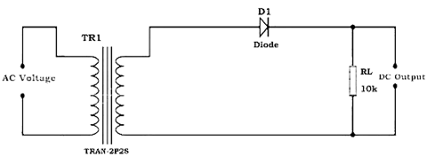
The half wave rectifier is a type of rectifier that rectifies only half cycle of the waveform. This article describes the half wave rectifier circuit working. The half rectifier consist a step down transformer, a diode connected to the transformer and a load resistance connected to the cathode end of the diode. The circuit diagram of half wave transformer is shown below:
Working of Half Wave Rectifier:
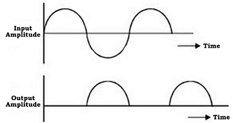
The input given to the rectifier will have both positive and negative cycles. The half rectifier will allow only the positive half cycles and omit the negative half cycles. So first we will see how half wave rectifier works in the positive half cycles.
Positive Half Cycle:
(i) In the positive half cycles when the input AC power is given to the primary winding of the step down transformer, we will get the decreased voltage at the secondary winding which is given to the diode.
(ii) The diode will allow current flowing in clock wise direction from anode to cathode in the forward bias (diode conduction will take place in forward bias) which will generate only the positive half cycle of the AC.
(iii) The diode will eliminate the variations in the supply and give the pulsating DC voltage to the load resistance RL. We can get the pulsating DC at the Load resistance.
Negative Half Cycle:
(i) In the negative half cycle the current will flow in the anti-clockwise direction and the diode will go in to the reverse bias. In the reverse bias the diode will not conduct so, no current in flown from anode to cathode, and we cannot get any power at the load resistance.
(ii) Only small amount of reverse current is flown from the diode but this current is almost negligible. And voltage across the load resistance is also zero.
