The magnetic circuit is shown in Fig..
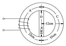
The m.m.f. (or AT) produced on the half A acts across the parallel magnetic circuit C and D. First, total AT across C is calculated and since these amp-turns are also applied across D, the flux density B in D can be estimated. Next, flux density in A is calculated and therefore, the AT required for this flux density. In fact, the total AT (or m.m.f.) required is the sum of that required for A and that of either for the two parallel paths C or D.
Value of flux density in C = 1.0 Wb/m2
Mean diameter of the ring = (24 + 18)/2 = 21 cm
Mean circumference = π × 21 = 66 cm
Length of path A or C = 66/2 = 33 cm = 0.33 m
Value of AT/m for a flux density of 1.0
Wb/m2 as seen from the given B.H characteristics = 900 AT/m
∴ Total AT for path C = 900 × 0.33 = 297. The same ATs. are applied across path D.
Length of path D = 18 cm = 0.18 m
∴ AT/m for path D = 297/0.18 = 1650
Value of B corresponding to this AT/m from given table is
= 1.45 Wb/m2
Flux through C = B × A = 1.0 × 9 × 10−4 = 9 × 10⁻⁴ Wb
Flux through D = 1.45 × (3 × 0.4 × 10−4 ) = 1.74 × 10⁻⁴ Wb
∴ Total flux through A = 9 × 10⁻⁴ + 1.74 × 10−4 = 10.74 × 10⁻⁴ Wb.
Flux density through A = 10.74 × 10⁻⁴ /9 × 10−4 = 1.193 Wb/m2
No. of AT/m reqd. to produce this flux density as read from the given table = 1200 (approx.)
∴ Amp-turns required for limb A = 1200 × 0.33 = 396
Total AT required = 396 + 297 = 693
