+1 vote
in Mathematics by kratos

An alternating current bridge is arranged as follows: The arms AB and BC consists of non-inductive resistances of 100-ohm each, the arms BE and CD of non-inductive variable resistances, the arm EC of a capacitor of 1 μF capacitance, the arm DA of an inductive resistance. The alternating current source is connected to A and C and the telephone receiver to E and D. A balance is obtained when resistances of arms CD and BE are 50 and 2,500 ohm respectively. Calculate the resistance and inductance of arm DA.

Draw the vector diagram showing voltage at every point of the network.

1 Answer

+1 vote
by kratos
 
Best answer

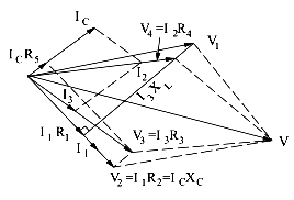
The circuit diagram and voltage vector diagram are shown in Fig..

As seen, I2 is vector sum of IC and I3.

Voltage V2 = I2 R2 = IC XC.

Also, vector sum of V1 and V2 is V as well as that of V3 and V4. IC is at right angles to V2

Similarly, V3 is the vector sum of V2 and ICR5.

As shown in Fig.,

R1 = R2 x R4/R3 = 50 x 100/100 = 50Ω

The inductance is given by

L = CR2(R4 x R5 x R4R5/R3)

∴ L = 1 x 106 = 50(100 x 2500 x 100 x 2500/100)

= 0.2505H

...